
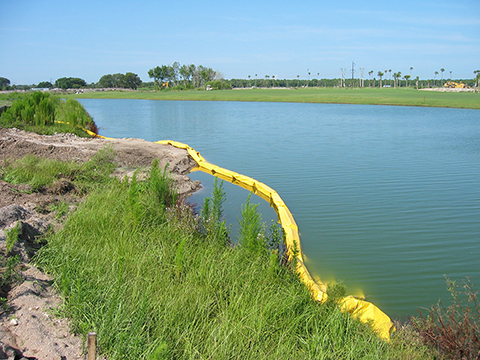
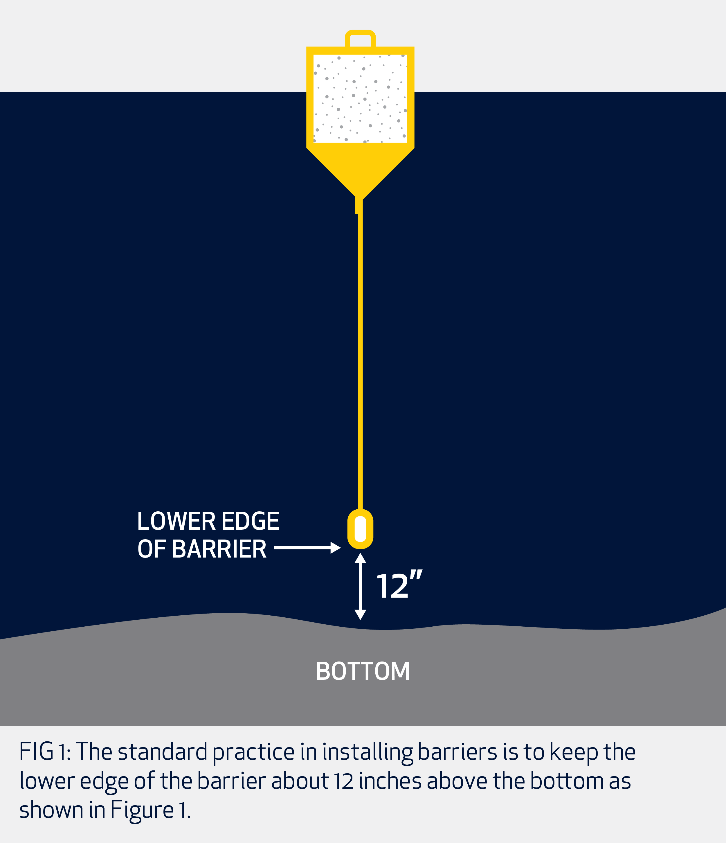
FIG 1: The standard practice in installing barriers is to keep the lower edge of the barrier about 12 inches above the bottom as shown in Figure 1.
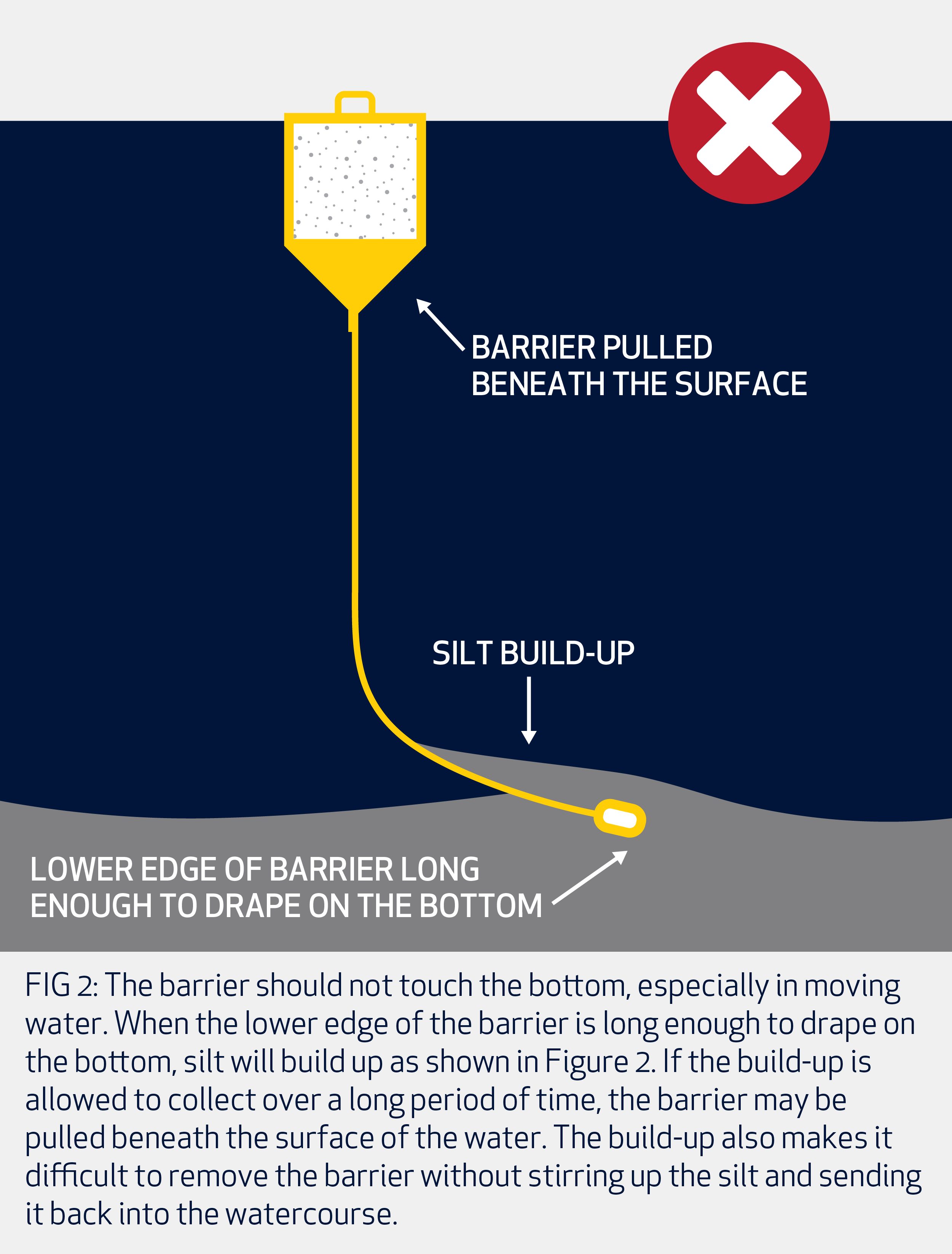
FIG 2: The barrier should not touch the bottom, especially in moving water. When the lower edge of the barrier is long enough to drape on the bottom, silt will build up as shown in Figure 2. If the build-up is allowed to collect over a long period of time, the barrier may be pulled beneath the surface of the water. The build-up also makes it difficult to remove the barrier without stirring up the silt and sending it back into the watercourse.
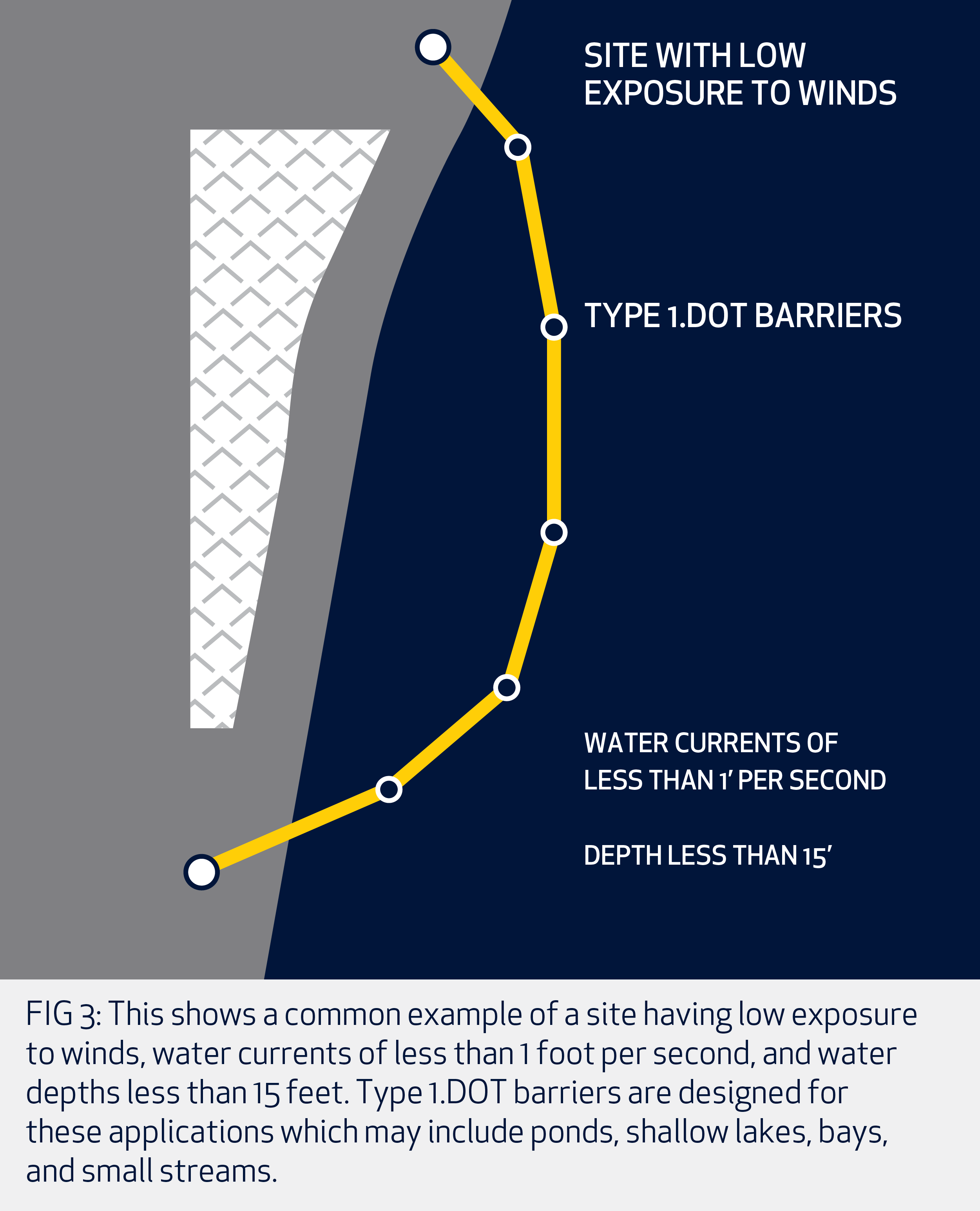
FIG 3: This shows a common example of a site having low exposure to winds, water currents of less than 1 foot per second, and water depths less than 15 feet. Type 1.DOT barriers are designed for these applications which may include ponds, shallow lakes, bays, and small streams.
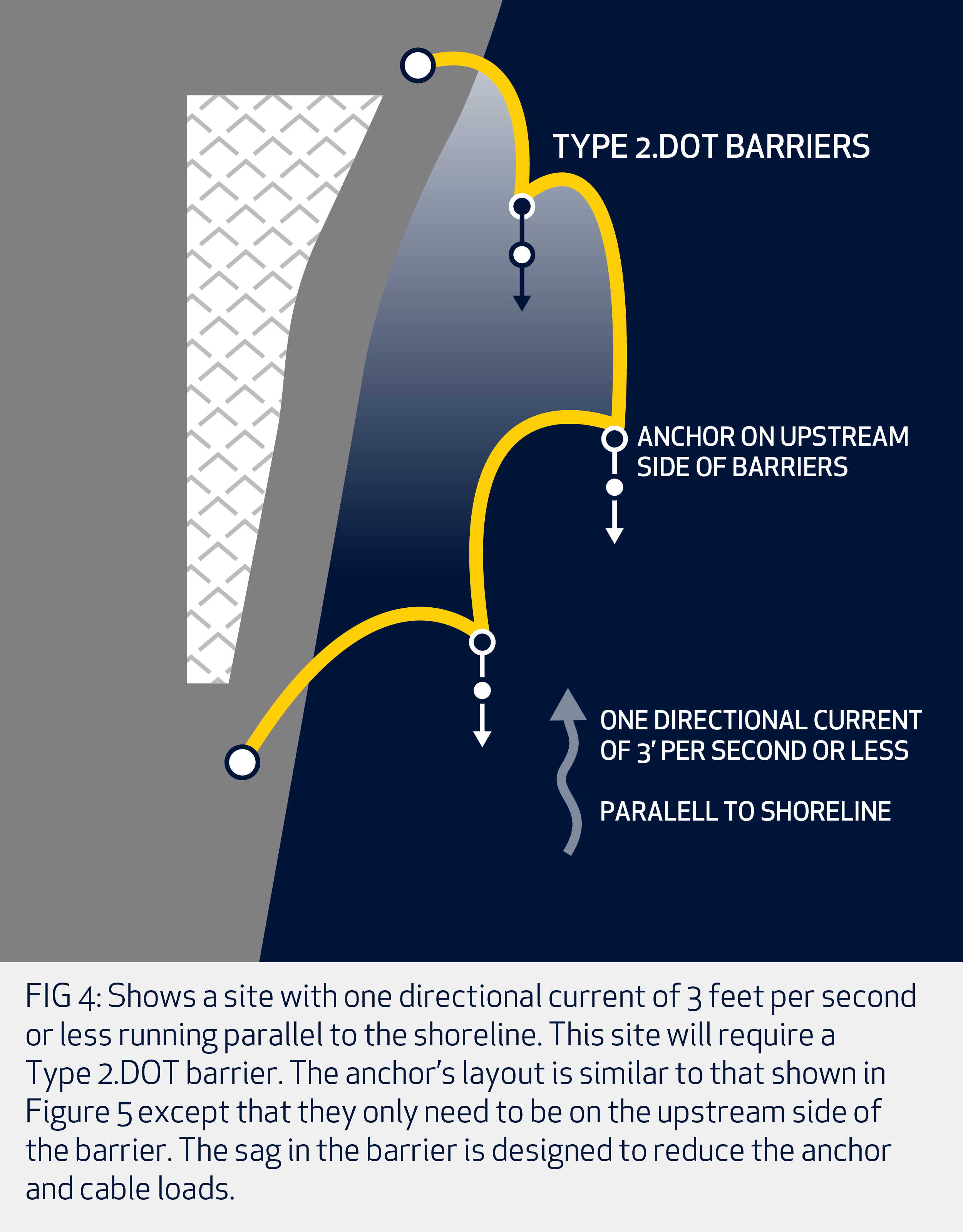
FIG 4: Shows a site with one directional current of 3 feet per second or less running parallel to the shoreline. This site will require a Type 2.DOT barrier. The anchor’s layout is similar to that shown in Figure 5 except that they only need to be on the upstream side of the barrier. The sag in the barrier is designed to reduce the anchor and cable loads.
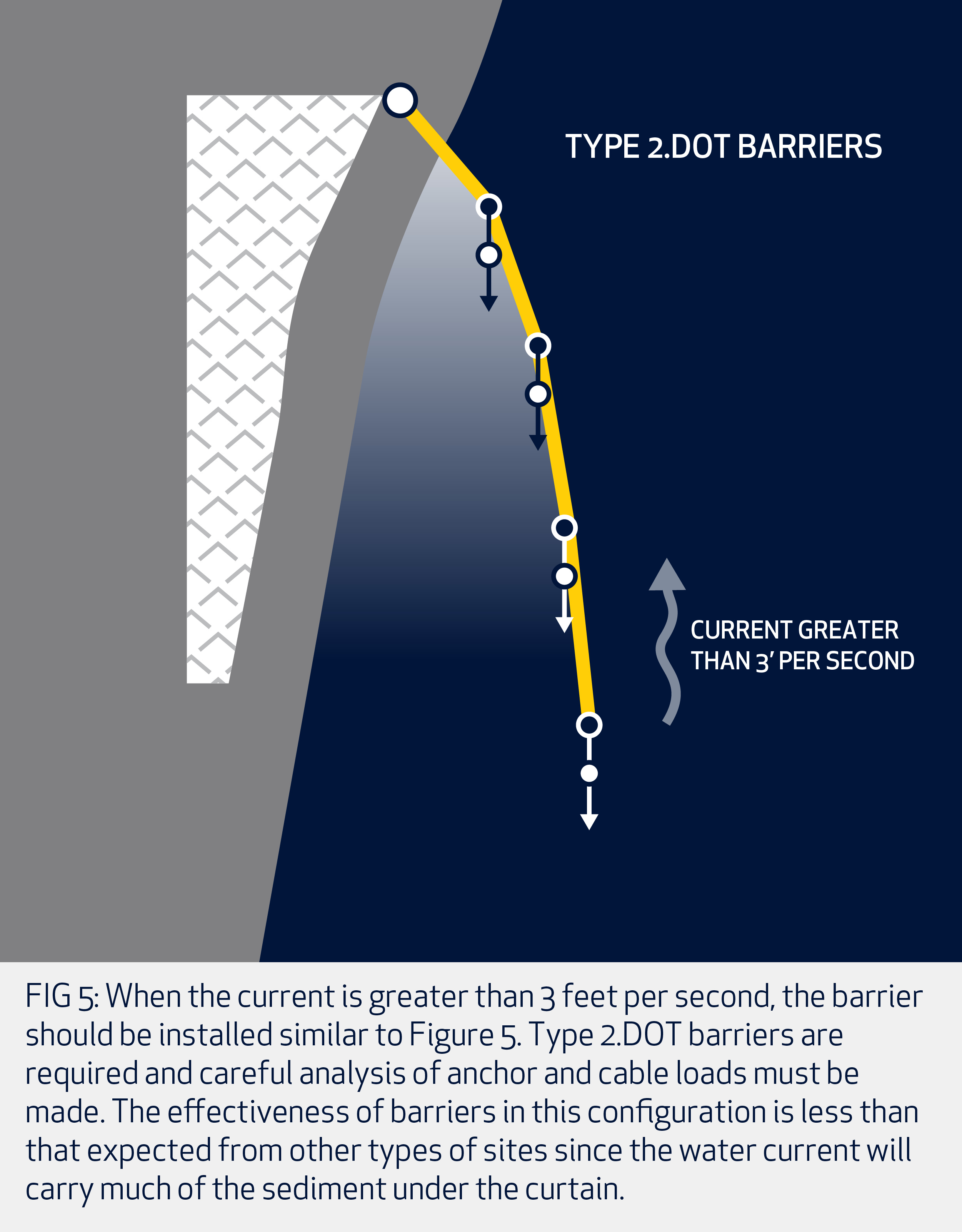
FIG 5: When the current is greater than 3 feet per second, the barrier should be installed similar to Figure 5. Type 2.DOT barriers are required and careful analysis of anchor and cable loads must be made. The effectiveness of barriers in this configuration is less than that expected from other types of sites since the water current will carry much of the sediment under the curtain.
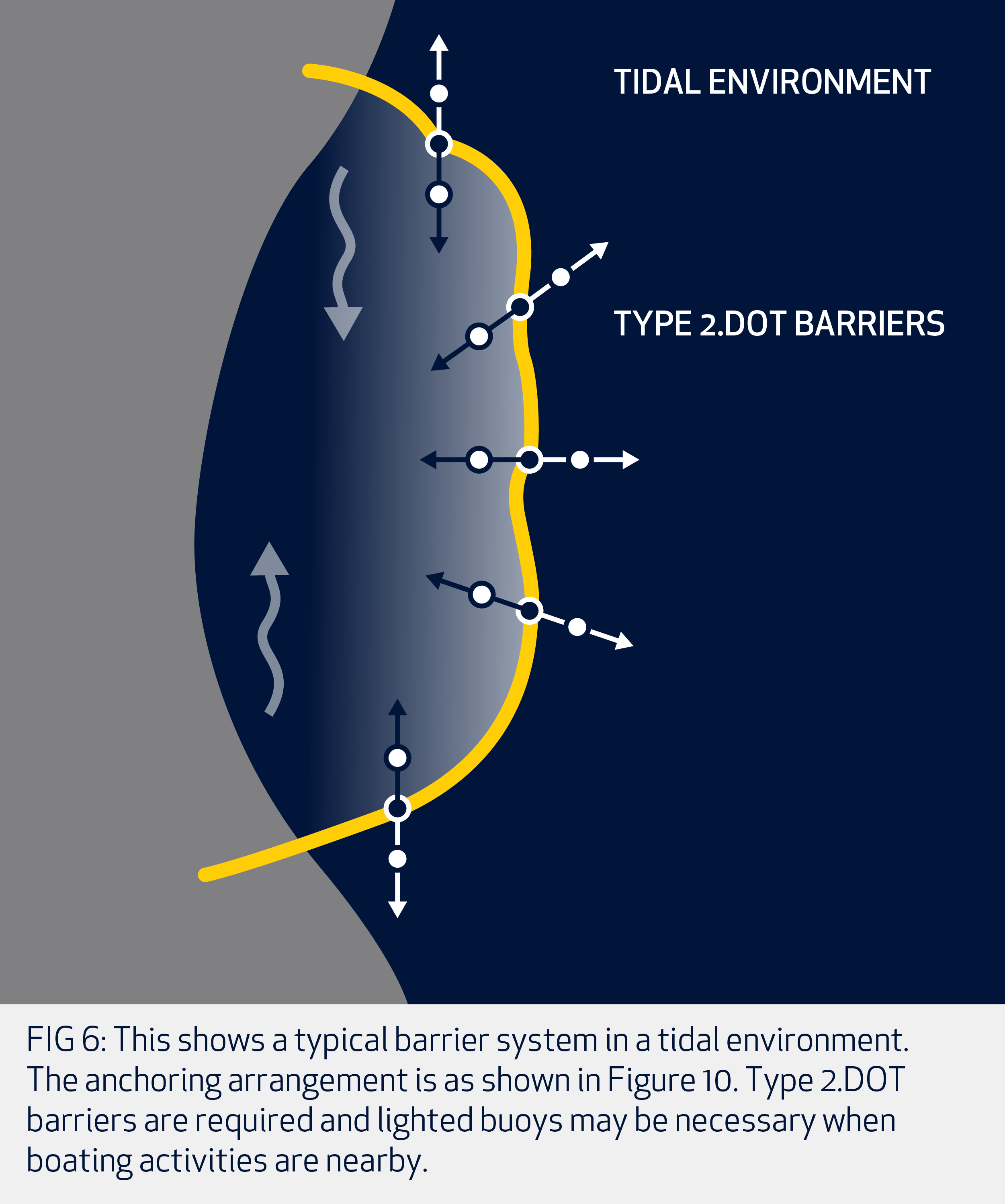
FIG 6: This shows a typical barrier system in a tidal environment. The anchoring arrangement is as shown in Figure 10. Type 2.DOT barriers are required and lighted buoys may be necessary when boating activities are nearby.
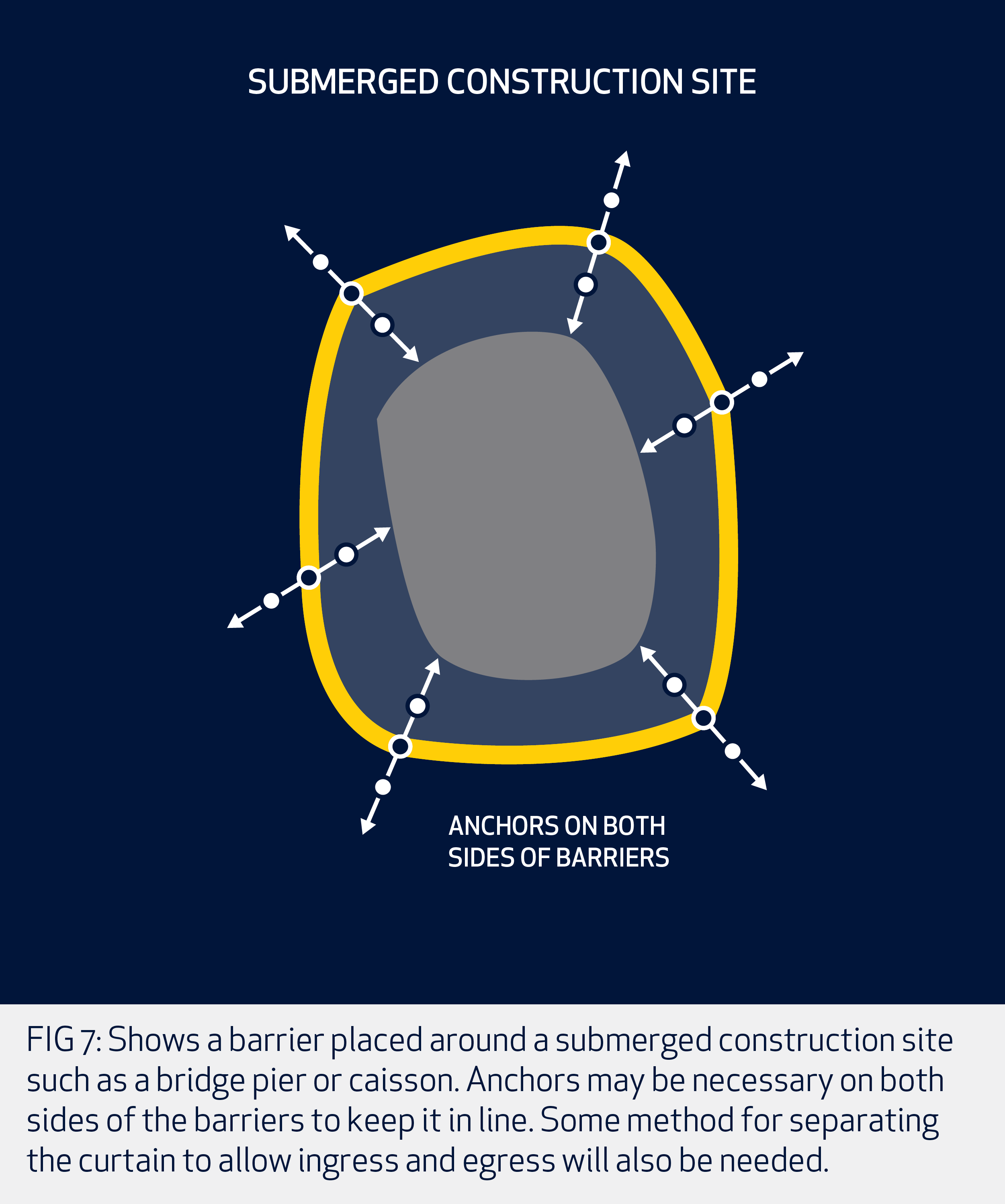
FIG 7: Shows a barrier placed around a submerged construction site such as a bridge pier or caisson. Anchors may be necessary on both sides of the barriers to keep it in line. Some method for separating the curtain to allow ingress and egress will also be needed.
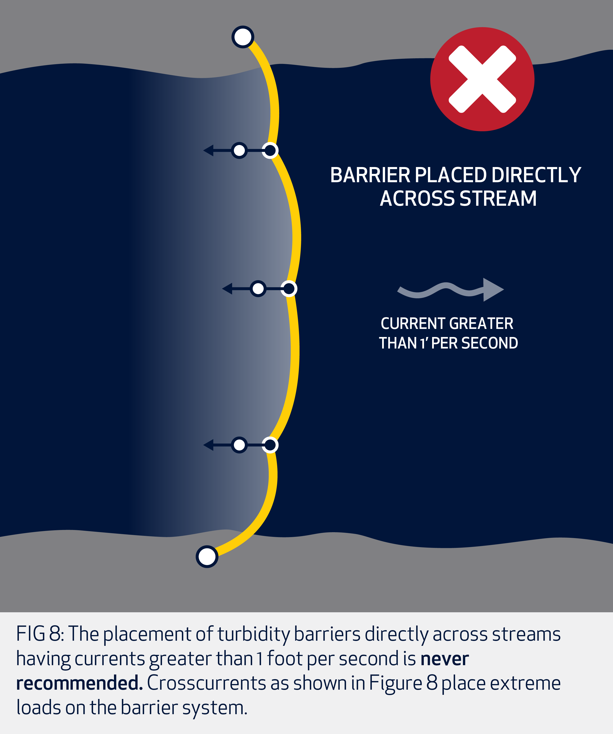
FIG 8: The placement of turbidity barriers directly across streams having currents greater than 1 foot per second is never recommended. Crosscurrents as shown in Figure 8 place extreme loads on the barrier system.
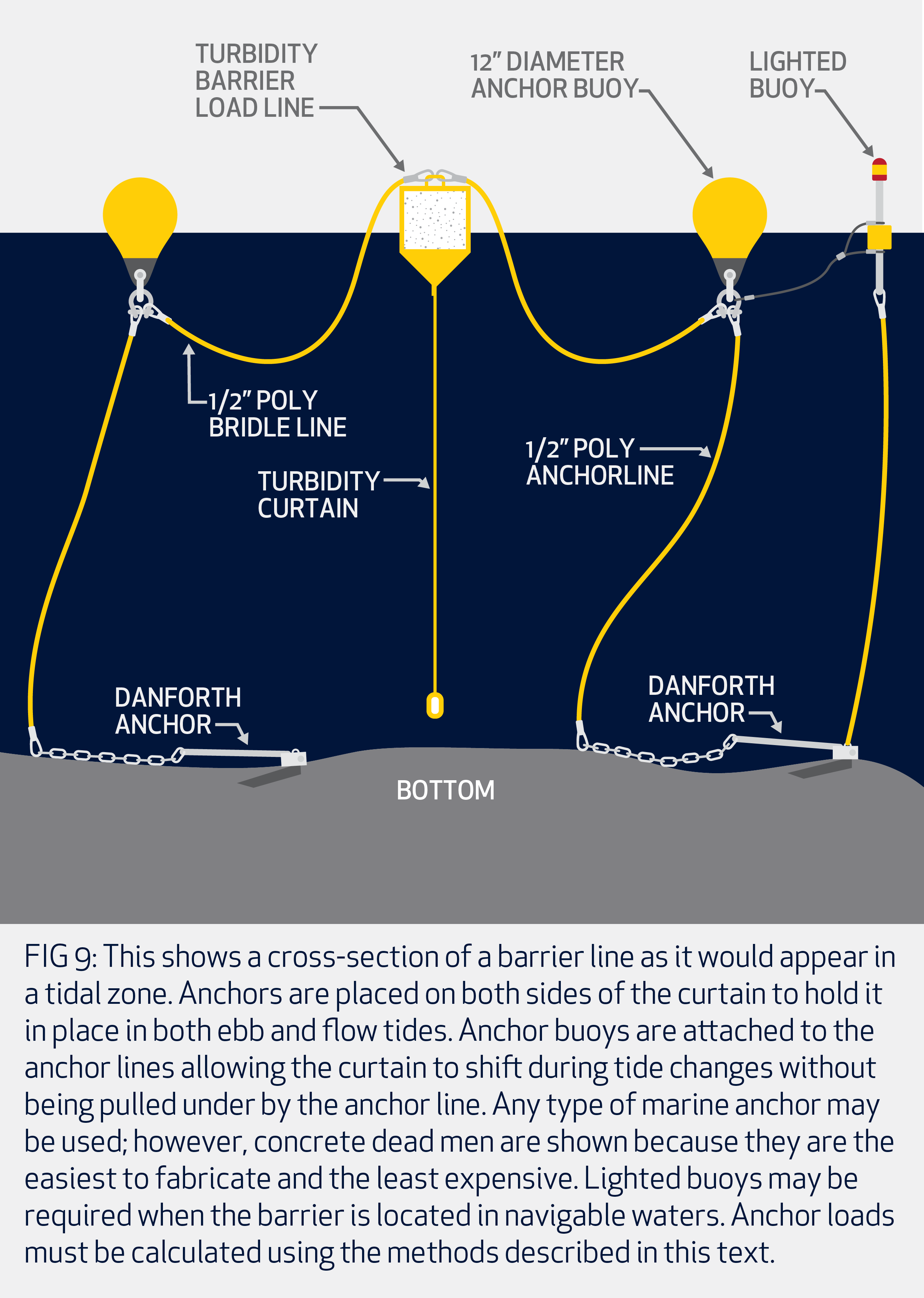
FIG 9: This shows a cross-section of a barrier line as it would appear in a tidal zone. Anchors are placed on both sides of the curtain to hold it in place in both ebb and flow tides. Anchor buoys are attached to the anchor lines allowing the curtain to shift during tide changes without being pulled under by the anchor line. Any type of marine anchor may be used; however, concrete dead men are shown because they are the easiest to fabricate and the least expensive. Lighted buoys may be required when the barrier is located in navigable waters. Anchor loads must be calculated using the methods described in this text.
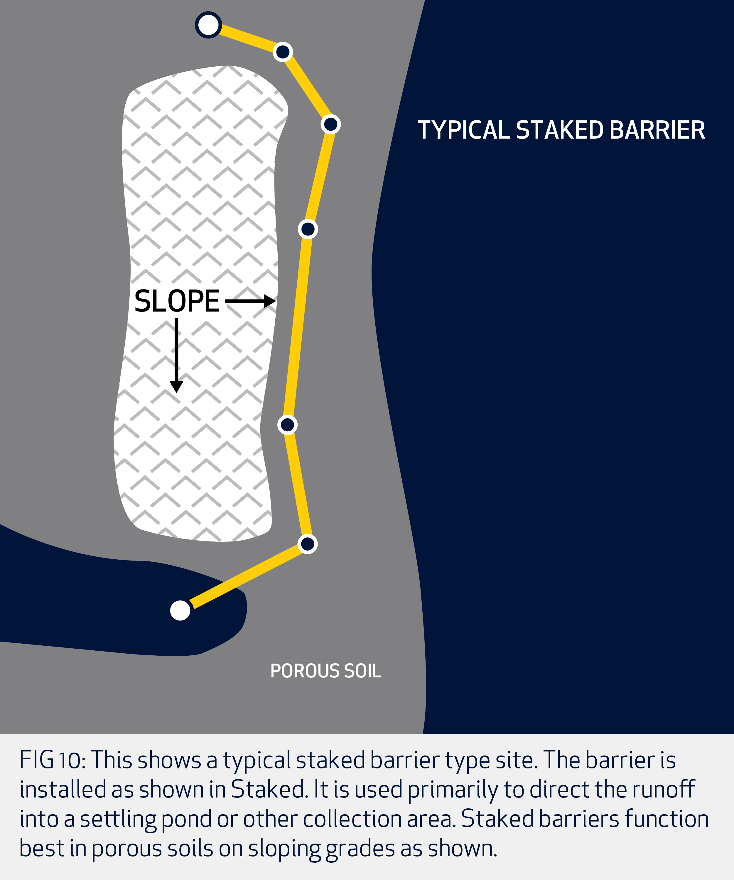
FIG 10: This shows a typical staked barrier type site. The barrier is installed as shown in Staked. It is used primarily to direct the runoff into a settling pond or other collection area. Staked barriers function best in porous soils on sloping grades as shown.
VIEW ILLUSTRATIONS“Aer-Flo is incredibly reliable. When they say they will take care of something, you know it will be done.”
— Texas Distributor —
“Aer-Flo is the go-to company for all environmentally sensitive projects.”
— Alabama Distributor —
“I’ve never had an issue with an order being fulfilled. They always get it done.”
— Florida Distributor —
“In today’s environment, getting products out to customers isn’t easy for some companies. But for Aer-Flo, this isn’t an issue. If they say they’ll get you the product, they do it.”
— Alabama Distributor —
“It is VERY easy to get a hold of someone at Aer-Flo and get questions answered and get real, live help with orders.”
— Florida Distributor —

 4455 18TH STREET EAST, BRADENTON, FL 34203
PH: 941.747.4151 FX: 941.747.2489